Practical advice
- Pull the plug out of the socket before carrying out any work on the power tool.
Set the required cutting depth and position the power tool with the front section of the planer base plate (9) on the workpiece.
- Only bring the power tool into contact with the workpiece when switched on. Otherwise there is danger of kickback if the cutting tool jams in the workpiece.
Switch on the power tool and guide it over the surface of the workpiece, applying uniform feed.
To achieve high-quality surfaces, apply only a low feed rate and exert pressure on the middle of the planer base plate.
For the processing of hard materials, such as hardwood, and also when utilising the maximum planing width, set only a low cutting depth and reduce the planer feed as appropriate.
Excessive feed reduces the quality of the surface finish and can lead to the chip ejector quickly becoming blocked.
Only sharp planer blades achieve good cutting performance and make the power tool last longer.
The integrated parking rest (19) also enables a continuation of the planing procedure following interruption at any point on the workpiece:
- Place the power tool – with parking rest folded down – onto the area of the workpiece that you will continue to work on.
- Switch the power tool on.
- Shift the contact pressure onto the front of the planer base plate and slowly slide the power tool forward (➊). In doing so, the parking rest will swivel upwards and out of the way (➋), meaning that the rear section of the planer base plate is in contact with the workpiece again.
- Guide the power tool over the surface of the workpiece, applying uniform feed (➌).
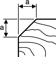
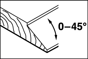
The V-grooves in the front of the planer base plate enable quick and easy chamfering of workpiece edges. Select the V-groove that corresponds to your chamfering width. Then position the planer with the V-groove onto the edge of the workpiece and guide it along.
| Groove used | Dimension a (mm) |
None | 0–4 | |
Small | 2–6 | |
Medium | 4–9 | |
Large | 6–10 |